Machine Specifications
MODEL
MACHINE VOLTAGE
STROKE-RAPID TRAVERSE
ROTATION
CONSTRUCTION
TABLE SIZE
TABLE TYPE
TABLE MANIFOLDS
VACUUM PUMP TYPE
MAIN SPINDLE
ATC
COOLING SYSTEM
INVERTER
C.N.C. CONTROL
OPERATOR PANEL
LUBRICATION SYSTEM
MACHINE COLOR
SAFETY DEVICES
T 1105 3626
As per customer’s requirements.
X/3,600 – 84 meters/min (142”-3307”min)
Y/2,600 – 84 meters/min (102.3”-3307”min)
Z/1,200 – 40 meters/min (47.24”-1574”min)
A Axis +/-120 degrees 30 rpm
C Axis +/-360 degrees 30 rpm
Moving bridge type
3,640 mm x 2,140 mm. (143”X 84”) table
Standard phenolic clamping surface, machined with 10 mm grooves on 30 mm centers with M8 threaded vacuum opening on 150 mm centers, complete with one removable center safety wall.
Twin 10 place vacuum manifolds
2 Pieces, Becker KVT 100, 5 HP, 100 CMH.
10 kW, 13 hp, from 1,000 to 22,000 rpm
8 tool changing magazine
8 tool holders HSK 63 F with CCT treatment
8 collets
Liquid/refrigerator
15 kW up to 22,000 rpm
Fanuc 180i-MB5, with Ethernet, 20 Gb memory P, 5 simultaneously interpolated axes, CNC display unit with Windows XP Pro.
1 piece, mounted on overhead movable arm.
Automatic by oil
Blue/yellow Multiax standard.
Mechanical Structure
01.1 – A moving bridge type machine with a fixed worktable divided in two vacuum independent zones. During machine operation the work piece is steadily clamped on one of the working tables while the operator can unload and load on the other for non-stop manufacturing.
The machine frame is constructed in engineered steel with supporting ribs and gussets. Dimensions and structural components have been studied according to dynamic principles to guarantee rigidity and torsional strength. All components are heat treat stabilized.


01.3 – Mechanical positioning system of X, Y and Z axes by linear motion guide rails of 35 mm in X, Y and Z. The guide rails are hardened and ground, coupled with quadro type roller bearings that support the movable parts.
01.4 ‑ Mechanical driving system of the X, Y and Z axes are by rack and pinion.
01.5 – Both sides of the bride are driven by a rack and pinion.
Electric/Electronic System and Safety Devices
02.1 – Main rotary switch with door-lock, fit for the connection to the power supply line and equipped with suitable safety protections. Such safety protections consist of an automatic voltage breaker in case of safety circuit stoppage.
02.2 ‑ Electric box equipped with safety mechanical devices with extractable key, consisting of:
– Electromagnetic switches
‑ Micro-relay for emergency line
– Electronic rapid fuses
– Sequence controller (PLC)
– Numerical control (NC)
02.3 – Air conditioning unit sized for keeping the maximum temperature inside of the electric box to 35 degrees C.
02.4 ‑ The electrical cabinet is fitted with thermal protection of motors consisting of overload relay and thermal probes to prevent any over-heating of the motors.

02.6 ‑ Electric safety devices with automatic feed-hold in case of:
a) Lack of vacuum
b) Pneumatic pressure drops
c) Intrusion in the “CE” safety device (if required)
d) General alarms
Lubricating System
03.1 – The machine is fitted with a centralized lubrication system by oil, complete with pump, pressure control to guarantee a regular and constant lubrication by pipes and valves, with flow of lubricating oil on the movable parts such as linear motion guides and bearings, guide rails, rack and pinion, ball screws.
03.2 – Self-diagnosis and alarm device in case of oil fault of the above-mentioned lubrication system, with alarm display on the main control panel.
03.3 ‑ Manual greasing points are clearly visible on all sliding parts of occasional and marginal use, requiring monthly or periodical lubrication.


Pneumatics
04.1 – The centralized pneumatic system equipped with de-humidifier filter unit with condensation exhaust valve and pressure regulator. This pneumatic system allows the driving of the different subsystems with direct control from operating program, along with eventual other systems for clamping the pieces with pneumatic vices, stoppers or any other additional air supplied devices.
04.2 – Solenoid valves for actuators operation by dry air, in compliance with the latest environmental anti-pollution regulations.
Numerical Control
05.1.a – Fanuc 180i MB5 full digital, LCD 10.4″ TFT color VGA, for high efficiency and performances, equipped with main following characteristics, expressly chosen for the best versatility and use in the specific field of woodworking consisting of:
– Main control CNC 32 bit
– Integrated PC with windows 2000
– 5 axes controlled simultaneously
– Least input increment 1 micron
– Helical interpolation for spiral machining
– Part program storage on hard drive of 20 GD
– Program input from the keyboard or floppy disc and/or RS 232
– Exponential type acceleration and deceleration on each axis, settable by parameters
– Tool offset and tool length compensation
– Backlash compensation
– Self-diagnosis and alarm history display
– Acceleration/deceleration axis, “linear” type
– Eventual additional options such as background editing, memory expansion, robot interface, etc.
– 600 blocks look ahead
07.2 – Jog pendant, and software for Fanuc 180i


Axis Control
06.1.a ‑ A.C., brush less servomotors, with integrated pulse encoder.
06.2 – The X, Y and Z axes are coupled directly to a gearbox with rack and pinion with inclined teeth. The gearbox is mounted on preloaded guides to compensate automatically any backlashes, through an elastic mechanism, for all the cycle of life of the machine. The ball screws, by ball nuts, as long as the rack and pinion, convert the rotary movement of each servomotor into linear movements, which interpolated by CNC, accurately perform the selected program.
06.3 ‑ The maximum positioning speed is 84 meters/min. (3,307”) for the X, 84 meters/min. (3,307”) for Y-axis and 40 meters/min. (1,575”) for Z-axis, achieving remarkable time saving.


Spindle Motor Drive
08.1‑ The motor is equipped with a static inverter unit of 15 kW. The inverter enables the rotation of the spindle motor from 1,000 to 24,000 rpm, programmable by NC.
Operation Panel
07.1 ‑ The Control Panel fitted on remote pedestal, movable and orientable in the most accessible position or in cabinet attached to the moving bridge and is equipped as follows:
Color LCD 10.4” which enables to visualize absolute positions, parameters and memory, diagnosis, alarms and all necessary functions for information and editing
- Alphanumeric keyboard
- On/off switch for vacuum pump
- Air alarm led
- Electric/electronic alarm led
- Lubrication alarm ledFeed rate switch (FEED RATE)
- Step button (SBK)
- Reset button
- Mode switch (MODE)
- Cycle start button
- Cycle hold button
- Selector for step movement of axes with 0.01-0.1-1 mm. scale
- Emergency stop button


Motor Drive
10.1‑ The motor is equipped with a static inverter unit of 15 kW. The inverter enables the rotation of the spindle motor from 1,000 to 22,000 rpm, programmable by NC.
Vacuum Clamping System
09.1‑ 2 Pieces, Becker KVT 100, 5 HP, 100 CMH.
Table Specification
10.1. – The work table is an 3,640 mm (143”) x 2,140 mm (84.2”), divided in two independent suction areas. During the work cycle the operator unloads and loads parts on one side of the machine table, while parts are being machined on the other side of the machine table. A safety wall is provided for separating the two work zones. The machine bridge will not enter the loading station until the operator is clear of the area.
10.2 ‑ Phenolic table surface has 10 mm grooved matrix on 30 mm centers with vacuum access holes every 150 mm for vacuum distribution. The table is complete with lateral references for rapid positioning of jigs and clamping.


10.3 – Twin 10 place vacuum manifolds connected to automatic vacuum valves controlled by the CNC, enables clamping the work pieces on one table, while the other table is inactive, for unloading and loading operations. The vacuum system includes a filter to prevent impurities inside the pump.
Spindle
12.1- The machine is equipped with one motor of 10 kW, 13 hp, up to 22,000 rpm, able to supply the whole nominal power starting from 10,000 rpm. In this spindle the rotor is equipped with 4 angular ceramic ball bearings on the frontal couple, long life lubricated, air cooled and with tool holder type HSK 63 F double lock safety mechanic arrest, hose cleaning device, aligning sensors for operator safety.
12.2 ‑ On the above-mentioned spindle, it is possible to use tool holders type HSK 63 F with collet chucks available to 25 mm. Such collet chucks guarantee near perfect centering of the tool and allow tool dimension as follows: maximum length 100 mm and maximum weight of 3 Kg.


12.3 – ATC magazine has a capacity of 8 tools, pitch between tools of 80 mm. located on the bridge of the machine to enable a quick and easy placing of tools.
12.4 – Standard supply includes 8 tool holders with lock nuts and 8 collets, diameter on request (available 3-25 mm every 1 mm and English sizes).

Extra Specifications
14.1 – Refrigerator unit, mounted on the outside shoulder of the machine, fit for cooling the spindle by forced liquid, in order to keep the temperature between a range of 24°C and 27°, especially during heavy Routing tasks.

14.2 – Z axis pneumatic balancing system.
14.3 – Dust package, the machine will be fitted with bellows on the two X axis rack & pinions and linear rails assembles, bellows will be fitted on the Y axis rack & pinion and the linear rails assembles, metal tape protection will be fitted on the Z axis linear rails. The electrical cabinet and all electrical boxes will be dust proof and all connections will be sealed for dust.


Safety Package
16.1 – Protection package, consisting of:
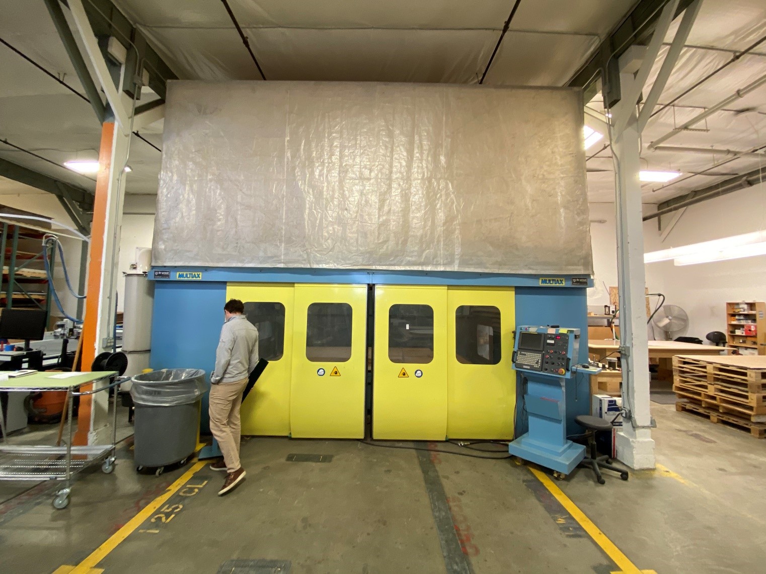
- Complete machine enclosure with the top of the machine fitted with fabric side walls and roof, for total protection of the complete operator area.
- Sides and back of machine are fully enclosed.
- Complete machine enclosure with two CNC controllable doors in front of the machine
- Removable center safety wall allows for load and unload the work piece while the machine is working on the other end.
- Total protection of the complete table front, when working large pieces.
Instructions and Operating Manuals
Machine Specifications
Axis
X Axis
Y Axis
Z Axis
A Axis
C Axis
Compressed Air:
Power Supply:
Machine Color:
Stroke Length – mm/inches
3,600 mm/142”
2,600 mm/102”
1,220 mm/48”
+/-120 degrees 30 rpm
+/-360 degrees 30 rpm
6 bar / 88 psi
30 kW 60 Hz voltage as required
Blue/yellow as MULTIAX standard
Rapid Travers Feed Rate – Meters/Inches/Min
84M/3,307”
84M/3,307”
40M/1,574”

